Lecture 36: Continuous Casting Processes (Part 2)
1. Components of a Continuous Casting Machine
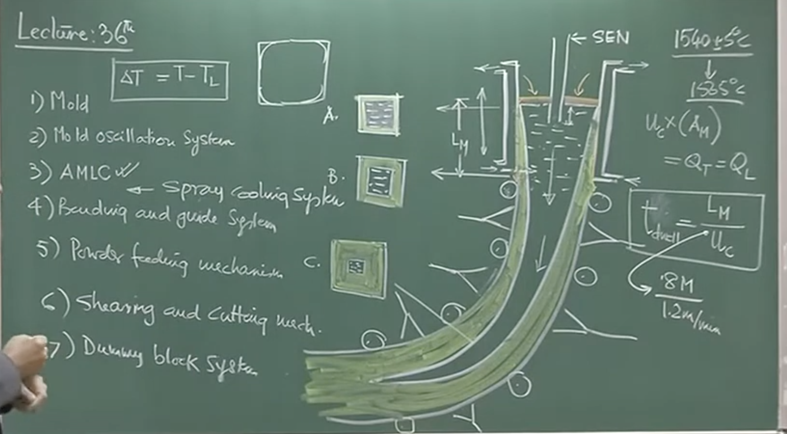
The continuous casting process involves several integral mechanical and control systems designed to extract liquid steel and shape it into a solidified strand continuously .
Essential Components:
-
Mold: A water-cooled copper mold where initial solidification occurs.
-
Mold Oscillation System: Moves the mold in a specific up-and-down trajectory along the curvature of the strand to prevent the solidifying steel from sticking to the mold walls.
-
Automatic Mold Level Controller (AMLC): A critical sensor-based system that maintains the liquid meniscus level at a steady state. If the meniscus level fluctuates, the distance between the Submerged Entry Nozzle (SEN) and the top of the liquid changes dynamically, causing operational issues. A continuous drop in the mold level might indicate a blockage (inclusion deposition) upstream in the tundish nozzle.
-
Bending and Guide Rolls: A set of mechanical rolls that guide the descending strand and bend it so it is discharged horizontally.
-
Powder Feeding Mechanism: Continuously replenishes the mold powder onto the liquid surface .
-
Shearing and Cutting Mechanism: Devices (such as an oxy-acetylene flame torch) that travel at the casting speed to chop the solidified strand into standard-sized billets, blooms, or slabs.
-
Dummy Block System: Plugs the bottom of the mold at the beginning of the casting sequence and is slowly withdrawn to guide the initial strand .
-
Spray Cooling System (Secondary Cooling): Applies intense cooling via water jets or air-mist to the hot strand right after it exits the mold.
2. Solidification and Cooling Zones
The Metallurgical Length
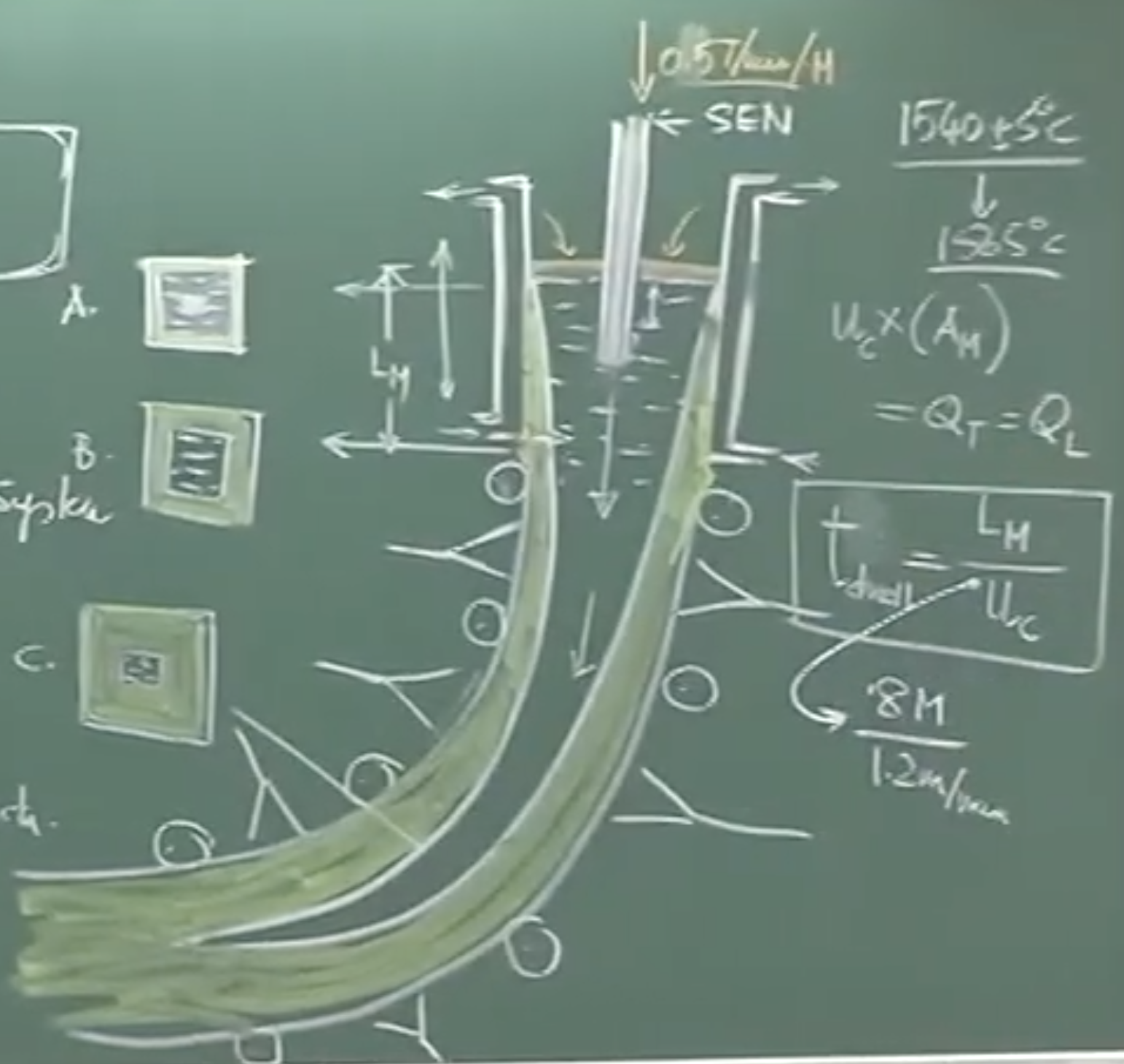
The metallurgical length is the total distance from the meniscus to the point where the central liquid core of the strand becomes completely solid .
-
At the Meniscus: Only a very thin film of steel is solidified.
-
At the Mold Exit: The shell thickness has grown but must be thick enough to withstand the ferrostatic pressure of the liquid core (liquid steel has a density of ).
-
Below the Mold: The liquid core progressively shrinks until the entire cross-section is solid.
Important Remark: If the shell at the mold exit is too thin, the high ferrostatic pressure will cause strand bulging . If bulging is detected via thermocouple-driven alarms, the operator must immediately reduce the casting speed to allow more time for the shell to thicken.
Flow Rate and Dwell Time
For a steady-state operation, the volumetric flow rate of liquid steel from the tundish must equal the rate at which the solidified strand is withdrawn:
Where:
-
= Casting speed (withdrawal speed)
-
= Cross-sectional area of the mold
-
= Volumetric flow rate from Tundish
-
= Volumetric flow rate from Ladle
The time the steel spends inside the mold is called the Mold Dwell Time ():
Where: = Length of the mold.
Cooling Regions
Continuous casters have distinct cooling zones with entirely different heat extraction mechanisms:
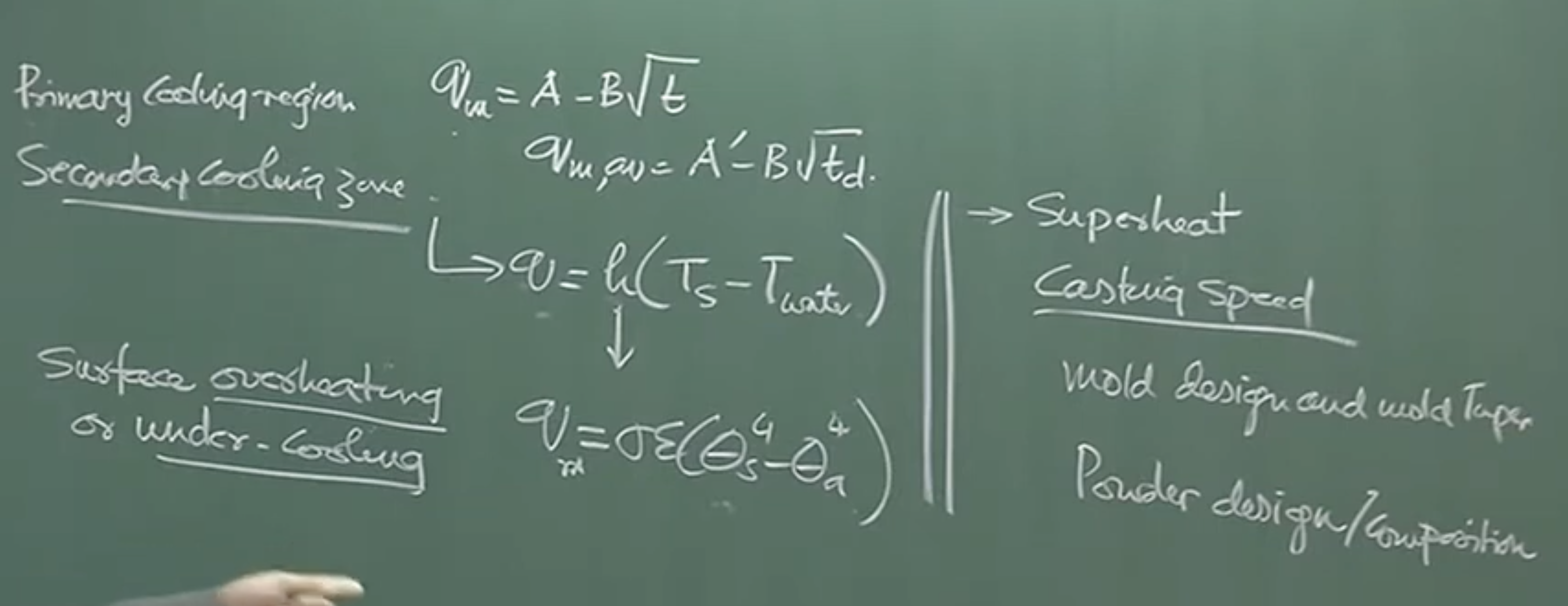
1. Primary Cooling Zone (The Mold):
-
Extracts superheat and forms the initial crust.
-
Heat transfer is relatively weak here due to the thermal resistance of the mold powder film and the air gap caused by steel shrinkage.
-
The heat flux decreases parabolically over time (or distance down the mold) due to the thickening solid shell:
2. Secondary Cooling Zone (Spray Cooling):
-
Occurs immediately below the mold using water jets or air-mist (air-water mixture) . Air-mist is preferred as it creates fine droplets, increasing the heat transfer area .
-
Extremely intense heat extraction. The spray droplets hit the steel surface (approx. 1100°C - 1400°C), triggering complex pool and nucleate boiling .
-
Governed by convective heat transfer:
Physical Interpretation / Instructor Note: The transition between the primary and secondary cooling zones is critical. If the first spray is drastically weaker or stronger than the cooling rate at the mold exit, the strand will suffer from surface overheating (remelting) or undercooling. Such thermal shocks generate enormous thermal stresses. It is widely accepted that almost all cracks seen in continuous casting originate due to irregularities within the mold or at this cooling transition .
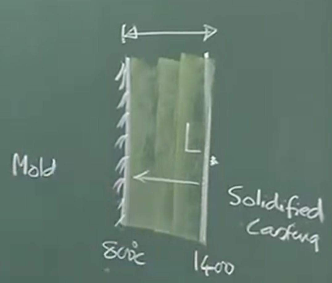
3. Roles of Mold Powder and Mold Taper
The gap between the water-cooled copper mold () and the solidified casting surface () is filled with mold powder .
-
Powder Phases: As the powder descends, it transitions from a dry unreacted powder at the top, to a crystalline layer, to a fully liquid slag layer in contact with the hot steel .
-
Roles: It insulates the top surface, captures rising inclusions, prevents oxidation, and most importantly, it regulates the heat extraction rate depending on its tailored composition .
As the steel solidifies and descends, it shrinks. To prevent the thermal gap from widening (which would drastically reduce heat extraction), the mold is deliberately designed with a taper . The taper angle must perfectly match the specific shrinkage profile of the steel grade being cast.
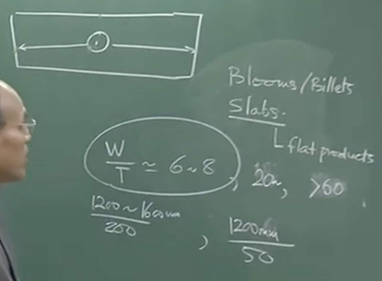
4. Bloom vs. Slab Casters
The geometry of the casting heavily influences fluid flow and heat transfer inside the mold.
-
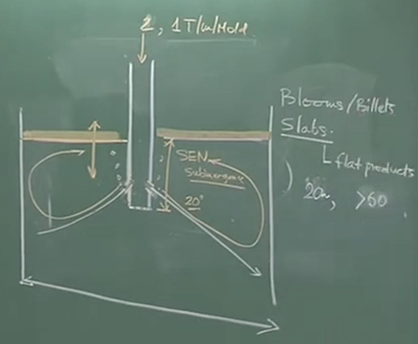
Blooms/Billets: Used mostly for long products (crankshafts, automotive parts). They have square or near-square cross-sections (e.g., 200x200 mm). The Submerged Entry Nozzle (SEN) utilizes a straight vertical discharge.
-
Slabs: Used for flat products (auto bodies, fridge panels). They possess a large width-to-thickness ratio (e.g., 200 mm thick but 1200 mm to 1600 mm wide).
 SEN Design for Slab Casters:
In a slab mold, the distance from the center to the wide face is 6 to 8 times greater than to the narrow face . A straight nozzle would cause localized freezing at the wide edges. Therefore, the SEN is designed with two bifurcated ports directing the molten steel outward towards the narrow faces, creating a characteristic twin-roll flow pattern.
-
SEN Port Taper Angle: Typically angled downward
-
If the taper is too steep, the flow will not circulate upward, leading to a cold meniscus.
-
If the taper is too shallow/upward, the violent flow will severely disturb the meniscus, causing the liquid steel to swallow slag droplets (entrainment).
-
5. Critical Operating Parameters and Defects
Running a continuous casting machine on a sustained, defect-free basis requires incredibly tight process control. The most critical parameters the operator must balance are:
-
Superheat ()
-
Casting Speed
-
Mold Design and Taper
-
Powder Characteristics
Superheat and casting speed share an inverse relationship. If a ladle arrives from the secondary metallurgy station with too high a superheat, the casting speed must be immediately lowered (which alters and spray routines) .
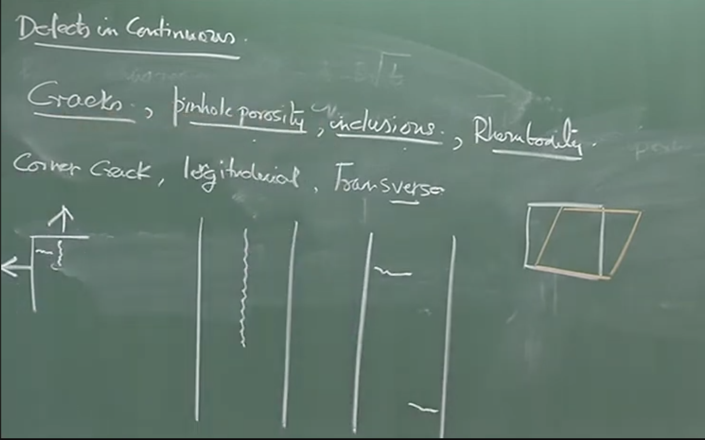 Common Defects in CC Products:
-
Cracks (Corner, Longitudinal, Transverse): Originate from faulty mold taper, incorrect powder thermal resistance, or rapid 2D heat extraction at the corners of the mold .
-
Pinhole Porosities: Caused by hydrogen precipitation.
-
Inclusions: Often triggered by mold powder entrapment. Detecting sodium or potassium in an inclusion proves it was exogenously sourced from the mold powder.
-
Rhomboidity: If the copper mold is impure, its high-temperature strength is compromised. The ferrostatic pressure forces the weakened mold to physically distort, causing a nominally square billet to cure into a rhombus shape .
6. Flow Control via Electromagnetics
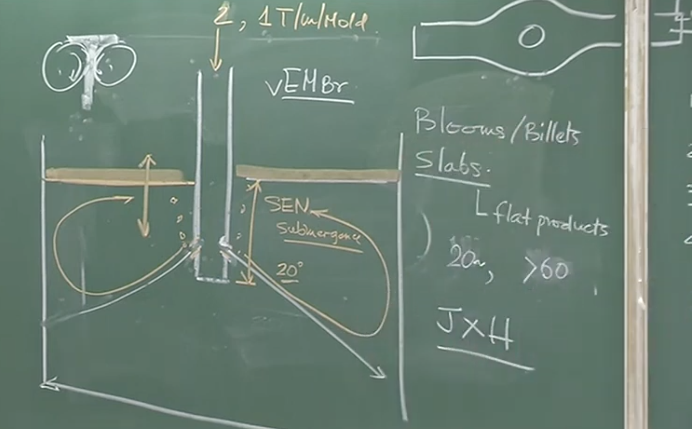
Depending on the casting geometry, we use magnetic fields to either artificially accelerate or dampen fluid velocities . Both rely on the Lorentz force ().
-
Electromagnetic Braking (EMBR): Used in slab and strip casters. Because the throughput () is massive and the mold dimensions are tight, the resulting jet velocities are dangerously high, threatening violent meniscus disturbance. EMBR uses strong magnetic fields to dampen and slow the internal fluid velocities without reducing the plant’s overall volumetric throughput.
-
Electromagnetic Stirring (EMS): Used in bloom and billet casters. Here, flow rates are naturally lower, which can result in poor mixing and long columnar crystal growth . EMS applies magnetic forces to intentionally stir the liquid core, homogenizing the temperature profile and breaking up the crystals.
Audio v2:
1. Essential Components of a Continuous Casting Machine
The continuous casting process utilizes eight critical components starting from the ladle, passing through the tundish, and exiting as a solidified strand:
-
Water-Cooled Copper Mold: The primary cooling zone where the initial solidified shell forms.
-
Mold Oscillation System: Operates on a cam mechanism with a fixed radius, moving the mold upward and downward along the strand’s trajectory to prevent the solidifying metal from sticking to the mold walls.
-
Automatic Mold Level Controller (AMLC): Sensor-driven system that keeps the liquid meniscus (liquid level) at a steady state.
- Exam Detail: If the mold level fluctuates dynamically, the distance between the SEN and the liquid changes. A continuous drop in the mold level indicates a blockage (deposition of inclusions) upstream in the tundish nozzle.
-
Bending and Guide Rolls: A mechanical system that guides the vertically descending strand and bends it so it discharges horizontally.
-
Powder Feeding Mechanism: Continuously replenishes mold powder onto the liquid surface as the casting shrinks and powder is entrained and flows out the bottom.
- Roles of Mold Powder: Shields molten metal from the air, captures rising inclusions, provides a thermal insulation layer, and regulates the heat extraction rate (thereby managing solidification rates and thermal stresses).
-
Shearing and Cutting Mechanism: Travels at the same speed as the casting strand to cut the metal into standard sizes (e.g., 4 or 5 meters).
- Exam Detail: An oxy-acetylene flame torch is commonly used for shearing billets or blooms.
-
Dummy Block System: Plugs the bottom of the mold at the start of the cast, follows the machine’s trajectory, and is withdrawn as the solidified strand begins to move.
-
Spray Cooling System: Located immediately below the mold; provides secondary cooling.
-
SEN (Submerged Entry Nozzle): Note: Transcribed as ‘acn’. The refractory artifact that sits between the tundish and the mold. SEN Submerged Depth is a critical parameter; if it is too shallow, it leads to severe operational problems.
2. Solidification and Casting Parameters
The growth of the solidified shell is critical for machine stability and safety.
-
Metallurgical Length: The total distance from the meniscus down to the point where the central liquid core completely vanishes and the strand is 100% solid.
-
Ferrostatic Pressure & Shell Thickness: At the mold exit, the solid shell must be thick enough to withstand the ferrostatic (hydrostatic) pressure of the liquid core.
-
Exam Detail: 1 meter of liquid steel has a density of 7000 kg/m³, exerting immense pressure.
-
If the shell is too thin, the pressure causes strand bulging. If bulging occurs, thermocouple-driven alarm systems alert the operator to reduce the casting speed, increasing the time the steel spends in the mold to grow a thicker shell. The extreme worst-case scenario of a thin shell is a breakout.
-
-
Dwell Time (): The time the steel spends in the mold.
-
Calculated as:
-
Exam Detail: If casting speed is 1.2 m/min and the distance is 0.8 meters, the dwell time is roughly 40-45 seconds.
-
-
Volumetric Flow Rate: At steady state, . (e.g., A 2-ton/min ladle throughput split across 4 strands = 0.5 tons/min per mold).
3. Heat Transfer and Cooling Zones
Continuous casting features distinct cooling regimes:
Primary Cooling Zone (The Mold):
-
Heat extraction here is relatively weak due to contact thermal resistance (the gap between the mold and the steel).
-
Temperatures: Copper mold wall is ~800–900°C (copper melts at ~1080°C, so it must be cooled efficiently). The solidified steel surface is ~1400°C.
-
Mold Taper: As steel solidifies, it shrinks. The mold is tapered to accommodate this shrinkage and maintain a uniform gap (approx. 1 mm or less) to ensure consistent thermal resistance.
- Exam Detail: Shrinkage depends on steel composition. Peritectic steels shrink differently than normal steels due to phase volume changes during transformation reactions.
-
Mold Powder Profile: Within the gap, the powder exists in different states: liquid (touching the 1400°C steel), semi-liquid, crystalline, and solid powder (touching the mold).
-
Heat flux obeys a parabolic rate law of solidification, dependent on the square root of dwell time.
Secondary Cooling Zone (Spray Cooling):
-
As the strand exits the mold, it meets water jets or air-mist cooling (air-water mixture creates fine droplets for massive surface area and heat transfer).
-
Temperatures: Surface drops to 1100–1200°C. The water is ~30°C. This creates pool and nucleate boiling, forming a gas/vapor envelope around the strand.
-
Overheating vs. Undercooling: The cooling transition from the mold to the first spray must be smooth. If the spray is too weak, surface overheating and remelting occur. If too strong, undercooling induces severe thermal stresses.
Tertiary Cooling (Radiation Zone):
-
Governed by .
-
Stacked billets in the yard have surface temperatures of ~800°C and core temperatures of ~1200°C. Massive amounts of energy are radiated here, prompting modern efforts to capture this heat to reduce specific energy consumption and promote “green” steelmaking.
4. Mold Geometries: Bloom vs. Slab Casters
When integrating the thermochemical outputs of the ladle refining furnace with the caster, the geometry of the target product drastically alters fluid dynamics in the mold.
-
Blooms/Billets (Long Products): Square or near-square cross-sections (e.g., 200x200 mm or 100x100 mm). Used for automotive parts, crankshafts, etc. The flow design is simpler because the distance from the SEN to the mold walls is uniform and short.
-
Slabs (Flat Products): Rectangular cross-sections (e.g., 200 mm thick, but 1200 mm to 1600 mm wide). Used for auto bodies and appliances. Modern slabs can reach up to 3 meters (9 feet) wide.
SEN Design for Slab Casters:
Because the distance to the narrow face is 6 to 8 times longer than the distance to the wide face, a single vertical port will not distribute heat properly.
-
Slabs use a bifurcated SEN with two ports pointing outward toward the narrow faces.
-
This creates a characteristic twin-roll flow pattern.
-
Port Taper: Typically 15° to 20° downward.
-
If the taper is too steep (downward), the flow won’t turn back up, resulting in a cold meniscus.
-
If the taper is too shallow (horizontal or upward), it violently disturbs the meniscus, causing the steel to swallow/entrain liquid slag droplets.
-
5. Managing Superheat and Casting Parameters
The caster operator designs the powder, spray cooling, and withdrawal speeds around a specific target temperature.
-
Superheat: .
-
If a ladle arrives from secondary metallurgy too hot (e.g., 1565°C instead of a target 1540±5°C), the operator cannot wait. Because superheat and casting speed have an inverse relationship, the operator must lower the casting speed, rework the spray cooling, and potentially alter the powder composition on the fly.
The Four Most Critical Factors for Defect-Free Casting:
-
Superheat
-
Casting Speed
-
Mold Design & Taper
-
Powder Characteristics
6. Common Casting Defects
Virtually all cracks in continuous casting originate in the mold due to faulty powder design, poor mold design, or erroneous casting parameters interacting with the high-temperature strength of the specific steel grade.
-
Cracks:
-
Corner Cracks: Caused by overly rapid 2-dimensional heat extraction at the corners.
-
Longitudinal & Transverse Cracks: Occur along or across the strand.
-
-
Pinhole Porosities: Caused by hydrogen gas evolution.
-
Inclusions: Often from mold powder entrapment. Exam Detail: Traces of sodium (Na) and potassium (K) in an inclusion are absolute proof of an exogenous origin (entrained mold powder).
-
Rhomboidity: If the copper mold contains impurities, its high-temperature strength drops. At 800-900°C, the ferrostatic pressure of the steel forces the weakened copper mold to deform, turning a square billet into a rhombus shape.
7. Flow Control Technologies (Electromagnetics)
To fix fluid flow issues without altering plant throughput, operators utilize the Lorentz Force () generated by huge magnets installed around the mold.
-
Electromagnetic Braking (EMBR): Used in Slab/Strip Casters. Because throughput is high, jet velocities from the SEN are extreme and can cause biased flow, remelting, or meniscus turbulence. EMBR dampens and slows the velocity fields to stabilize the flow.
-
Electromagnetic Stirring (EMS): Used in Bloom Casters. Because the flow rate is lower, stirring is inadequate. EMS assists the flow, homogenizes the bath, and breaks up long columnar crystals to make the microstructure more uniform.
8. Advanced Casting Technologies
-
Thin Slab Casters: Utilize a unique funnel-shaped mold. Width-to-thickness ratio is around 12. Standardized in plants like Tata Steel, JSW Dolvi, and AM/NS (Essar).
-
Twin Roll / Strip Casters: Molten metal forms a pool between two counter-rotating rolls. The metal emerges as a thin strip.
- Key Challenge: The dwell/contact time is on the order of milliseconds. Engineering extreme heat extraction within milliseconds to solidify the steel is the main hurdle. Often paired with Electric Arc Furnaces (EAF) for “endless strip casting.”